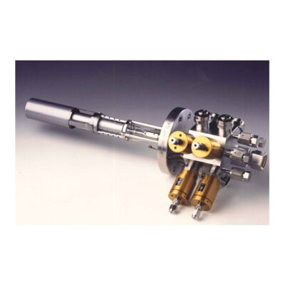
HTI – High Temperature Injector
Details
- Molecular beam with stable and uniform intensity
- Pneumatic run/vent valves – Easy mounting via VCR connections
- Dedicated model for high temperatures – Hydrides, ammonia,,..
- Field proven design
- Rugged, reliable for long lifetime
Presentation
Functions of gas injectors used in gas-source MBE and CBE systems are : (1) the introduction of a gas source into the epitaxy chamber, (2) the generation at the substrate of a molecular beam with stable and uniform intensity, (3) the pre-mixing of different gas sources of the same family within a single injector in order to achieve a high degree of material composition uniformity, and (4) the precracking of species, if required.
Depending on the nature of the precursor and its thermal stability relative to the growth temperature, the gas injector operates either at a low temperature (< 100°C, Riber’s LTI series) for preventing both condensation and dissociation of compounds before on-substrate cracking, or at a high temperature (> 600°C, Riber’s HTI series) to thermally decompose the molecular species before impinging on the substrate.
Riber gas injectors are fitted to the evaporation flange through a standard UHV flange, enabling installation on most gas-source MBE and CBE systems. Gas injectors feature independent 1/4 inch VCR® male gas inlets handling up to 2 distinct process gases, for LTI 163 series.
Gas injection lines are equipped with high temperature normally closed pneumatic actuators (200°C max.). Calibrated leak are installed at the run valve level in order to define the accessible flow range, fine adjustment is done via servo-valve, controlled via Baratron pressure transducer. The vent outlet is connected to a vent pump located in the CBr4 gas module (see dedicated page).
The source switching is based on a run/vent operation using a set of two-way valves for each gas line serving the injector. These valves are mounting via VCR connections at the back of the UHV flange. The “run” (to the substrate) and “vent” (to the vent pump) switching valves are located as close as possible to the epitaxy chamber to ensure rapid switching of sources with low transient times (< 1 sec) to produce abrupt layer interfaces.
Layout
Technical information
| Characteristics | HTI 163 | HTI440 2V | HTI440 4V |
|---|---|---|---|
| Pneumatic module | External | Injector body | |
| Maximum gas inlet | 1 | 2 | 4 |
| Number of Run actuators | 1 | 2 | 4 |
| Number of Vent actuators | 1 | 2 | 4 |
| Gas inlet | ¼ inch VCR® | ||
| Gas outlet | KF 16 | ||
| Typical operating temperature | 950°C | ||
| Maximum operating temperature | 1100°C | ||
| Heater | Single tantalum filament | ||
| Thermocouple | C type | ||
| Max Outgassing temperature | 1250°C | ||
| Mounting flange | CF63 / other with adapter flanges | ||
| Power supply | One power supply One temperature controller |
||


