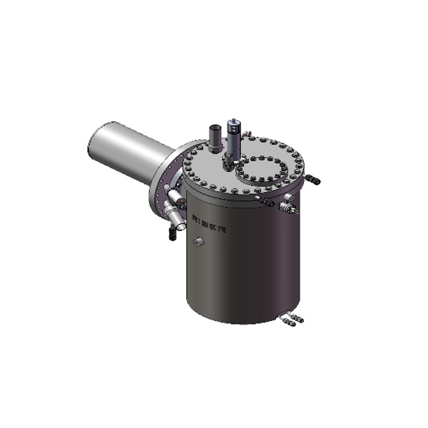
Valved Cracker Cell for Arsenic – VAC
Details
- More than 200 in operation
- Flux modulation reproducible within 1% with great valve dynamic response for total control of the growth
- Excellent flux uniformity for superior epiwafer quality
- Fast and precise on/off control over arsenic BEP
- Extended lifetime before refilling
- Rugged and reliable
Presentation
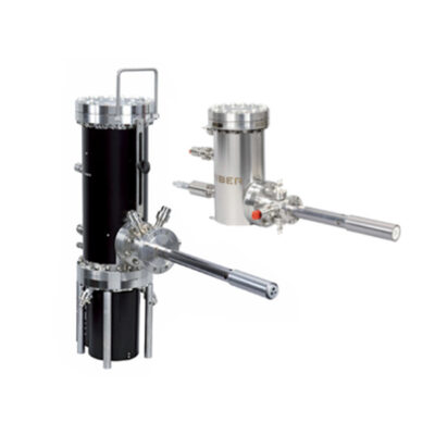
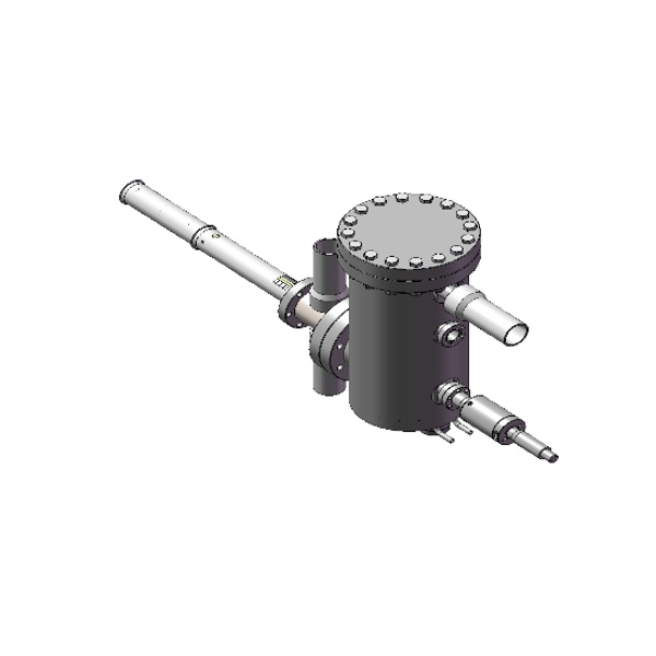
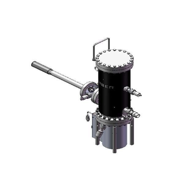
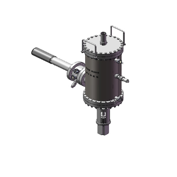
The Riber valve cracker consists of three main parts : the reservoir, the isolation valve and the cracker stage.
In addition to providing users with a large capacity arsenic source for increased system uptime, the valved cracker cell enables precise control over small or large variations in BEP with rapid shut-off capability. As well as easily isolating the bulk material from the epitaxy chamber, it also enables growth of advanced stacked structures, previously impossible to obtain using conventional MBE sources.
Vapor deposition with a VAC is the result of a Multiple Input Single Output structure base control :
-1st Input : The reservoir temperature controls the vapor pressure of metal in the crucible
-The crucible temperature determine the build up of vapor pressure in the crucible
-The crucible temperature stability warranty that the deposition rate is constant at a given valve opening
-2nd Input : The valve controls the conductance of the source
-For a given crucible temperature, the valve allows, to adjust the deposition rate over 3 decades
-For a given crucible temperature, the reproducibility of the valve position in Opening / closing cycles allows the reproducibility of deposition rate in the process.
Solid arsenic is loaded through a CF port into the reservoir crucible. The reservoir is externally water cooled for an efficient heat dissipation.
The metering valve is located downstream of the crucible, allowing exact control of the amount of As4 entering the feeding tube. This design allows the valve to operate at low temperatures and since it is thermally isolated from the cracker section, immediate start-up and long-term flux stability is achieved even if the cracker temperature is cycled. This valve is operated with an automated position controller.
The evaporated As enters a feeding tube and cracking zone where tantalum filaments resistively heat both assemblies. The cracker stage generates beams of cracked or uncracked material. Geometry of the diffuser has been optimized to provide a uniform flux on the substrate.
Layout
Technical information
| Cell characteristics | VAC 500 | VAC 3K | VAC 6K | VAC 20K |
|---|---|---|---|---|
| Filament | Two | Two | Two | Two |
| Heating filaments | Wire | Flat + Wire | Wire | |
| Thermocouple | Double C-Type | |||
| Useful capacity (Max load dimensions cc) | 550 | 2 900 | 6 000 | 20 000 |
| Mounting Flange (min) | CF 40 (2″ 3/4) | CF 63 (4″ 1/2) | CF 100 (6″) | CF 250 (12″) |
| Reservoir typical operating temperature | 400°C | |||
| Cracker typical temperature | 650°C -950°C | |||
| Temperature stability | +/-0.2°C | |||
| Valve characteristics | ||||
|---|---|---|---|---|
| Valve actuator | Micrometer drive | |||
| Stem Stroke | 1.5mm (3 revolutions) | 10 mm | 2 mm (4 revolutions) | 5.1 mm (8 revolutions) |
| Cracker Characteristics | ||||
|---|---|---|---|---|
| Max outgassing temperature | 1250°C | |||
| Power consumption | 300W max | 400W max | 1200W max | 2200W max |
| Reservoir characteristics | ||||
|---|---|---|---|---|
| Fill port diameter | 68 | 120 | 160 | 76 internal |
| Max outgassing temperaturer | 550°C | |||
| Power consumption | 300W max | 570W max | 640W max | 980W max |
| Water connection | Swagelok fitting Ø 6 female | |||
| Water flow | Min. flow 0.5l/mn 7 Bar max |
Min. flow 1l/mn 4 Bar max |
||

