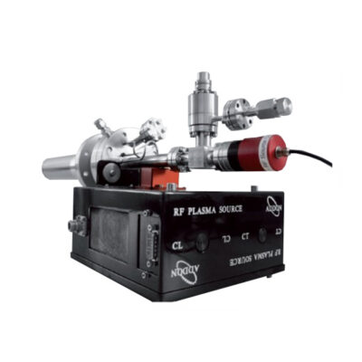
RF Plasma Source for Hydrogen – RF-H 600
Details
- Large range of adaptation for research & production
- Optimized reactive species production
- Perfect for wafer cleaning assisted by hydrogen: clean, smooth and preserved surfaces
- Efficient gas consumption and reliable design
- More than 50 high sources installed worldwid
Presentation
Riber offers the largest range of RF sources on the market today and cover customer needs from research to production.
Hydrogen RF sources is a key solution to assist wafers cleaning step, ensuring a smoother process than a simple thermal annealing, with lower thermal load transferred to the wafer, thus preventing surface degradation.
PBN materials for the discharge one-piece cavity is available to configure the source for reactive Hydrogen species.
The minimum source configuration requires a cavity + cell body and a matching box (comprising a RF generator, cables and water switch). An isolation valve is available for direct installation in the gas line.
Optical emission diagnostics (OED) can also be implemented onto the source for flux stability.
A shutter is available as an option.
Semiconductor grade gas panels are available for mass flow control, gas purification, and driving electronics. Dual gas injection panel is available in case gas mixing is requested.
Working principles
The RF plasma source operates by mean of an electrical field produced by the inductive coupling of the RF coil surrounding the cavity. A RF (13.56 MHz) generator delivers power to the discharge cavity space. To maximize power transfer to the plasma, a matching network is used to match the 50 Ohm impedance of the generator to the purely 50 Ohm impedance of the cavity load. Plasma in the cavity space produces atoms by dissociation of the molecular species. Atoms flow along with the non-dissociated molecules into the vacuum environment through an array of small holes at the front disk of the cavity. The hole arrangement is also called the «pattern». This pattern depends on application.
A large flux will require a large number of holes compared to an application where only a very small flux is required. Atoms generally have a very low recombination coefficient, so even those undergoing several wall collisions will ultimately contribute to the atom beam flux.
The electron sheet, covering the inside cavity walls, the hole sizes and shape are designed to minimize ions and electrons released from the cavity (Current lower than 10 nA / cm2).
Gas breakdown will occur above a certain pressure in the cavity. This pressure depends upon the gas ionization potential. As a result, and for a given cavity pattern, the flow rate of molecular gas will vary from gas to gas.
Plasma conditions is actively monitored via optical emission diagnostics to ensure flux stability and composition.
Layout
Technical information
| Characteristics | RF-H 600 |
|---|---|
| Cavity Material | PBN |
| Cavity type | One-piece cavity with patterned end |
| Mounting flange | CF 63 min –adaptations available |
| Tuning unit | Automatic matching box (2 modules) – manual version also available |
| Power supply | 600 W |
| Plasma observation viewport | CF 16 |
| Isolation valve | Included |
| Gas inlet | DN CF 16/ VCR ¼’’ |
| RF coil water cooling | Included–Ø6mm Swagelok connection DP>2 bars 0,3 l/min |
| RF tuning unit cooling | Air |
| Water security switch | Included |
| Options | Plasma optical emission detection |
| Deflection plates | |
| Shutter | |
| Gas panel + mass flow controller | |
| Gas purifier panel |


